August already and we are starting to lift our heads above the parapet whilst concerned about any surge of visitors down to Cornwall and what might follow. I mentioned in the July issue a new noise from the front of my engine and a degree of slip from the fan. You guessed it. One new water pump later everything is now OK. Followed it up with a full lube service front to back. Now awaiting voluntary MOT.
I have had a lot of interest in the behaviour of oil filters and consequences for oil pressure on cold startup. In essence, if the filter on your vehicle is mounted with the open end pointing down it needs to have an anti-drain diaphram. Moss stock such a filter, GFE173 is the part number. If mounted hanging down it won’t drain when engine is switched off.
This one tickled me… Hello David,
I read the Newsletter article of the newest Safety Fast! (5/2020,page 57). Tony Taylor in the nice article wrote that he has replaced spring flowers in suspension springs.
Can I write an article about that in our Finnish MG Car Club Finland magazine “ Brittisportti” and publish the copy of that spring flowers picture, if I mention the origin of that article?
Best Wishes, Marja Silvasti – Lundell
The following is from Mike Barclay. Thanks Mike!
Mgb fuel gauge calibration.
On a recent visit to the supermarket I decided to take the “scenic” route home to give the car a run. Driving along I heard the unmistakable sound of a ticking SU fuel pump closely followed by the car coming to a halt. The gauge showed ¼ full, but I had run out of petrol. Luckily I always carry a small can of petrol in the boot, so was able to use this to get home. So with plenty of time on my side I decided to see if I could calibrate the gauge to read more accurately.
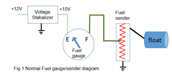
The fuel gauge in an MGB is very basic, consisting of a float connected to a variable resistor (sender unit) One end of the resistor is connected to ground, the other end is connected to one side of the gauge. The other side of the gauge is connected to the voltage stabilizer. (fig1)The gauge consists of a heater coil and bi-metallic strip with a pointer attached. When the ignition switch is turned on, current flows causes the heater coil to heat and the bi-metallic strip to deflect and pointer to move, indicating the fuel reading on the gauge. (The reason the gauge is slow to response) Moving the float up or down changes the resistance, causing a respective change in current through the heater coil and the amount the bi-metallic strip/pointer deflects.
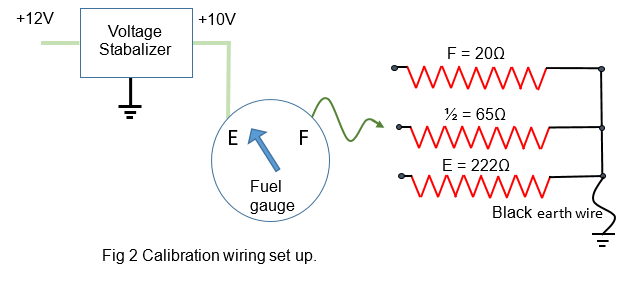
To check the calibration of the gauge all that is required is to substitute the sender unit with resistors who’s known values represent a definitive value on the gauge.
Full 20 Ω
¾ 35 Ω
½ 65 Ω
¼ 105 Ω
Empty 222 Ω
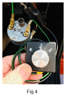
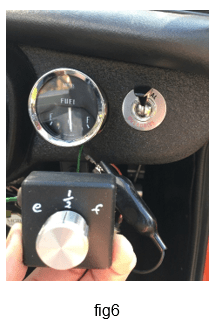
I decided that I was really only interested in the E(Empty), ½ and F (Full) values, so looking on the RS website ordered the required 20 Ω, 18 and 47 (65 Ω) and surprisingly a 221 Ω resistor. I also ordered some 1Ω resistors for final value tweaking. The resistors cost pence but you have to buy a min qty of 10 per value. I rummaged around the garage and found a switch and small plastic box. When the resistors arrived i rummaged around the garage and found a switch and small plastic box and made up a little unit that allowed me to switch between E, ½ and F with a croc clip connecting to earth and a lucar connector to connect to the gauge. (See fig 4.)
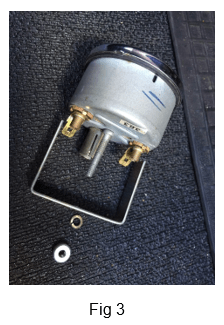
To remove the gauge, first put your hand under the dash and undo the small knurled nut on the back of the gauge, remove the washer, earth lead and U shaped bracket. (See fig 3). The black earth wire is only for the gauge lighting but is a handy ground connection for one end of the resistor.
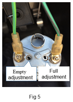
With the gauge removed Looking at the rear you will see two holes with small screw driver slots. See fig 5) These are the adjusters for setting the E and F calibration points.
As you look at the front of the gauge, the adjuster behind E to ½ , adjusts the E(Empty) pointer position. The adjuster behind the 1/2 to F adjusts the F(Full) pointer position.
Next on the rear of the gauge you will see two wires. A light green/dark green tracer wire that connects to the voltage stabilizer(10v) and a dark green/brown tracer wire that comes from the sender unit. Remove the dark green/brown wire from the gauge and in its place attach one end of the 222 Ω (E value) to the gauge. Connect the other end of the resistor to the Black earth wire.
OK we are ready to start calibrating. However two things I learned and to be aware of before making any adjustment.
The screw driver adjustments, particularly the Zero are very crude, the slightest movement can cause quite a large change in pointer movement.
Secondly the two adjustments (Empty and Full) interact with each other.
One last thing before we start. Either make sure the gauge housing is not connected to or touching ground or ensure the blade of your screw driver is insulated as the adjusters are connected to the gauge electrical circuit and could damage the stabilizer if shorted out. .
Turn on the ignition and allow the gauge to read. Remember the gauge is slow to respond so allow 20 – 30 seconds between any adjustments. With the 222 Ω resistor, the gauge should read E but in my case was reading ¼ full. So bearing in mind the above I opted for the ½ and ½ approach. Using a small screwdriver I turned the Empty adjuster to position the needle so it now showed half way between ¼.and E.(Half the original reading) Replacing the resistor with the 20 Ω value to represent a F (full tank). (This is where my little switch box made this easier) allowing 20-30 seconds for it to stabilize my gauge now read just over ¾ full. So with my screw driver in the FULL adjustment hole adjusted the needle to read half way between the original reading and F. Then replacing the resistor again with the empty value (222 Ω) allowed for the needle to stabilze at the zero end. Again making an adjustment to half the error then repeating with Full resistor value. Repeat this until the gauge gives the correct readings at Full and Empty with one final check at ½ full. My gauge seems to have some hysteresis as when going from F to ½ the gauge read exactly ½ (see fig 6), but when going from E to ½ it read just under the ½ mark. In all this took me around 30 mins.
Turn off the ignition and reassemble the gauge into the dash.
TIME WARP
by Colin Grant
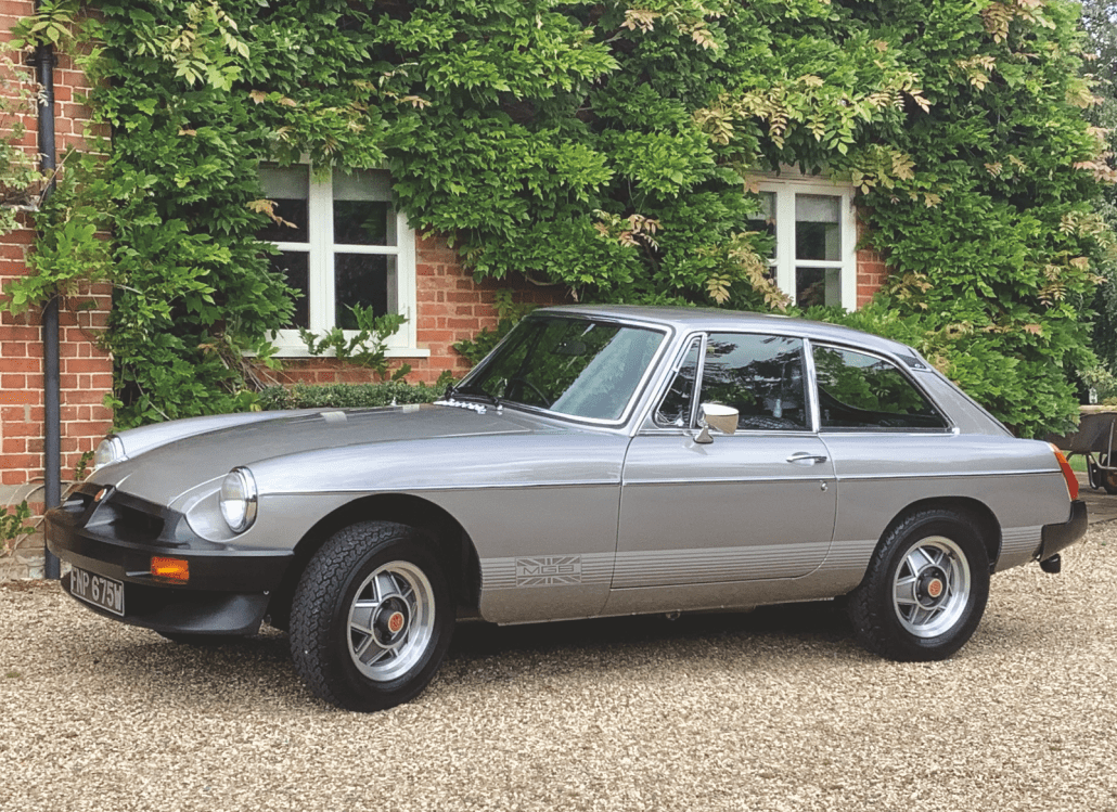
The MGB and GT LEs were the last of the line and were produced to celebrate 50 years of MG production and sadly to mark the end of production at Abingdon on October 24 1980. The cars were equipped with overdrive, Silver LE decals, front spoiler, and special limited edition badging. The roadster had the option of cast alloy or wire wheels (212 cars were fitted with alloy wheels and 208 cars had wire wheels) and the GT was only fitted with the distinctive alloys.
They were produced in special paintwork of Pewter metallic for the GTs with silver stripes, and Bronze metallic for the roadsters with gold stripes running the length of both cars’ bodywork. The inside of the roadster was finished in orange and brown striped cloth trim, with the GT in a silver grey interior. The cars were originally priced at £6,445 for the roadster and £6,937 for the GT. A total of 1,000 LEs were produced with 420 roadsters and 580 GTs. But sales were not brisk and many didn’t sell until the early eighties. The very last of each model went to the British Motor Museum at Gaydon.
Last LE GT pictured by Harry Grant in the factory compound during 1980
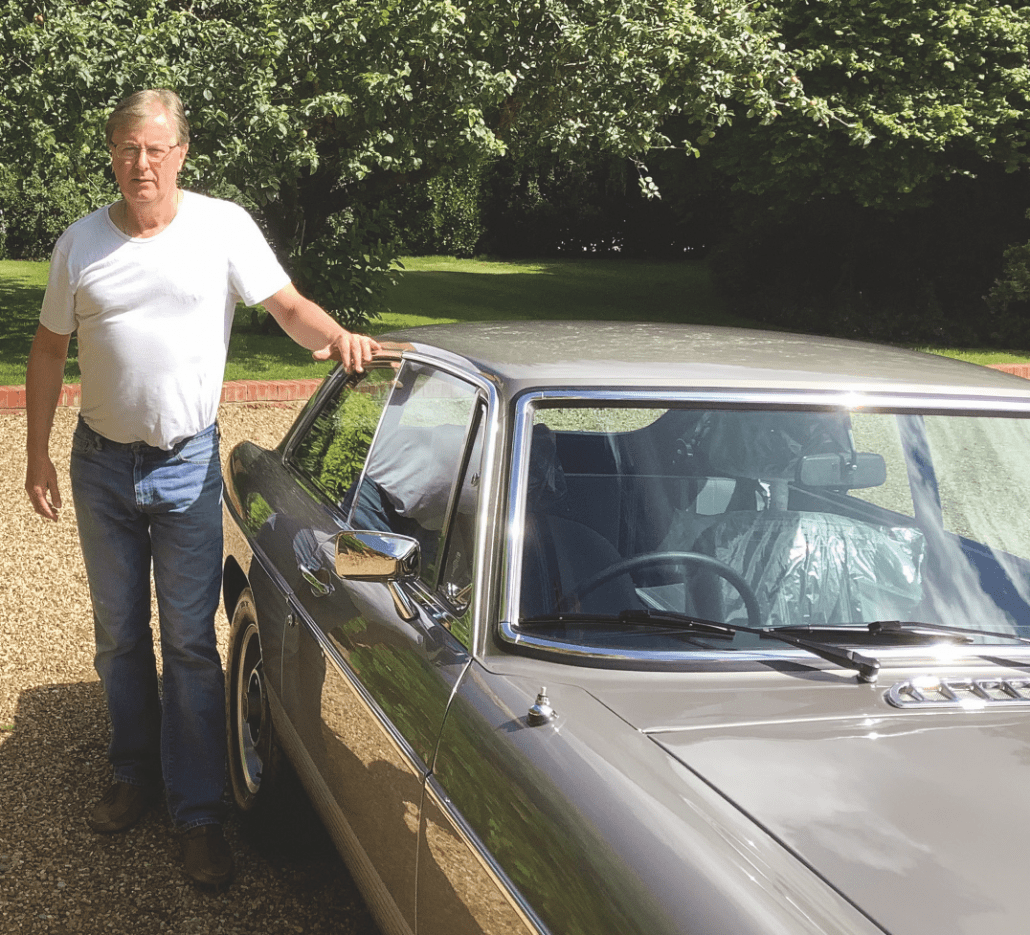
The car was originally purchased by a Mr A. Graves from a dealer in Lancaster called Oliver Rix Garage on July 14 1980, and the invoice shows he paid £5,278 plus £90 delivery charge. Tom has all the original documentation that would have come with the car.
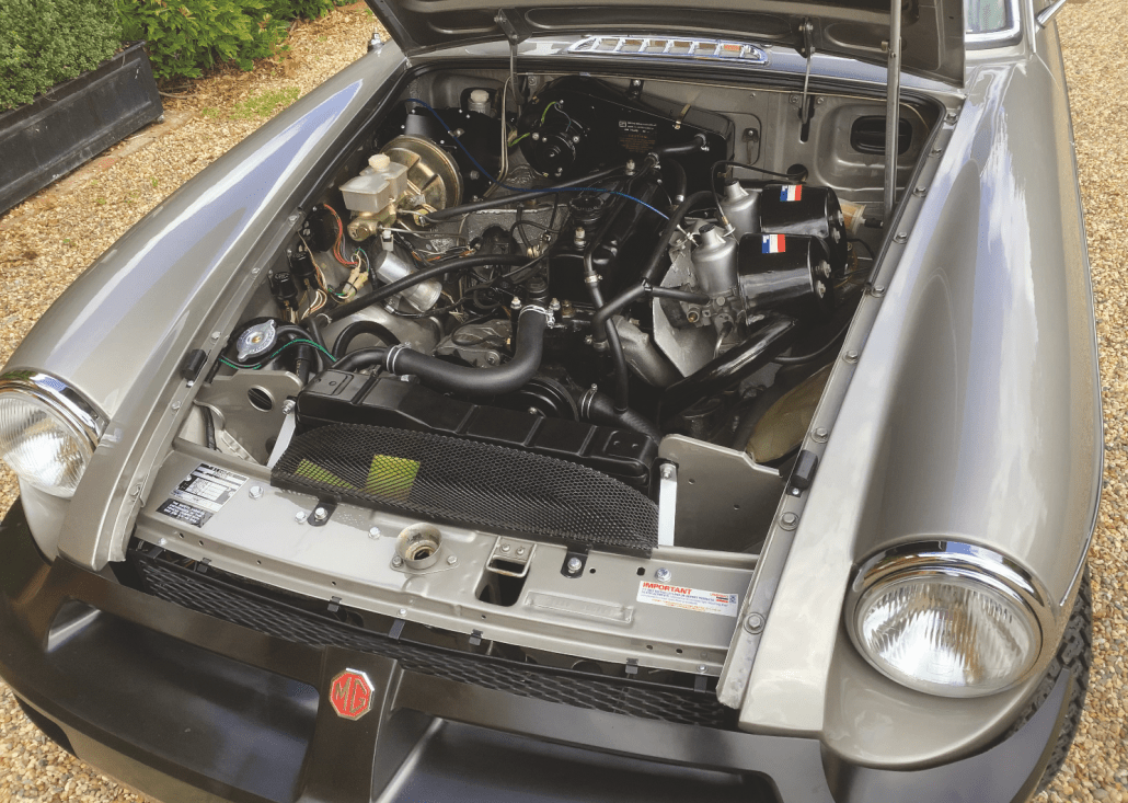
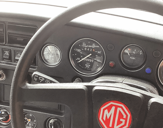
The car has been so well stored that even the tyres and other rubber items show no signs of deterioration as you would normally expect on an unused car of this age. All stickers are in place as can be seen from the photos. There are even yellow chalk marks under the wheel arches and the original plastic covering for the seats and head restraints are all still in place.
Tom says he originally bought the car for his wife as a fun car and to rekindle his relationship with an MG, having owned a GT back in the 70s. But his wife, on seeing the car, felt she would be too nervous to drive such a rare car and it is now up for sale.
DAVID BROADHURST
newsletter-editor@mgb-register.org

